LEADING EDGE SELF RETRACTING LIFELINES
An Effective Alternative To Steel Cables
INTRODUCTION
Leading Edge Self Retracting Lifelines have traditionally been designed with heavy steel cables as it was a proven product that could pass the ANSI/ASSP Z359.14-2014 Standard. Until recently there were no alternate materials that could be used to pass this rigorous test which requires connecting a 282 lb. test mass to the SRL and dropping it perpendicularly and offset over a .005” radius steel edge. The test mass must swing unrestricted on the edge for 2 minutes to verify it will not separate and cause the weight to break free. After the two minute period, the sample must then be tensile tested and maintain a breaking strength greater than 1,000 lbs. An alternate method to not tensile test the sample after the 2 minutes is to substitute a 300 lb. test mass in place of the 282 lb. test mass.
STATEMENT OF PROBLEM
When a new product is introduced to an alternative time-tested product, there can be questions and skepticism as to how it will perform. This is especially true when the product you are developing is a critical lifesaving component in the fall protection industry. Even with the various standards that are put in place to protect workers, it is important to continuously test the product to meet and exceed those standards by testing above and beyond what a standard requires. Additionally, most standards call for products to be tested in a “new” condition vs. being tested what might be a “used” product in the field. If a product has been in the field and used over a period of time, will it still perform as intended? To address this, Sturges utilized one of its drop towers to see the effects of how a webbing leading edge lifeline would perform.
STUDY
Determine the performance of X-7352 D1 when subjected to both a Leading Edge and Post Leading Edge static strength test when subjected to the following.
- Offset Leading Edge test per ANSI/ASSP Z359.14-2014 with a 2 min unrestricted swing**
- Offset Leading Edge test per ANSI/ASSP Z359.14-2014 of samples subjected to abrasion testing per FED STD 191A Method 5309 prior to Leading Edge testing with a 2 min unrestricted swing**
- Offset Leading Edge test per ANSI/ASSP Z359.14-2014** (2 min unrestricted swing followed by 3 minutes of additional swing in the following configurations) 1. 1.5 min back and forth swing (perpendicular to the cutting edge), 1.5 min circular swing 2. 1.5 min side to side swing (parallel to the cutting edge), 1.5 min circular swing 3. 1.5 min side to side swing, 1.5 min back and forth swing
**Leading Edge tests were performed with the exceptions listed as follows. – Free Fall distance of the test mass was 6’6” – No retractor was used, the X-7352 D1 webbing was attached directly to the anchor point.
TEST PERFORMED
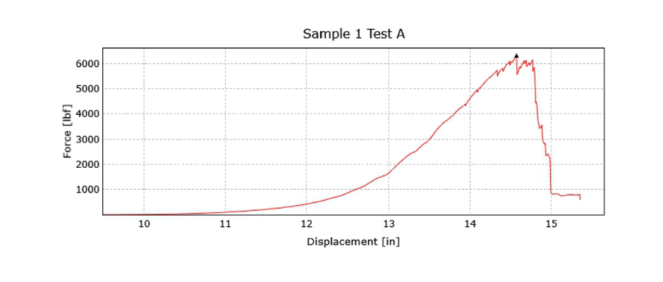
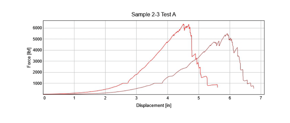
A. Leading Edge testing per ANSI/ASSP Z359.14-2014 was performed on 3 samples of X-7352 D1 to set a baseline for performance of this webbing under standard testing conditions. This test was done with a 300lb test mass and allowed to swing unrestricted for a minimum of 2 minutes.
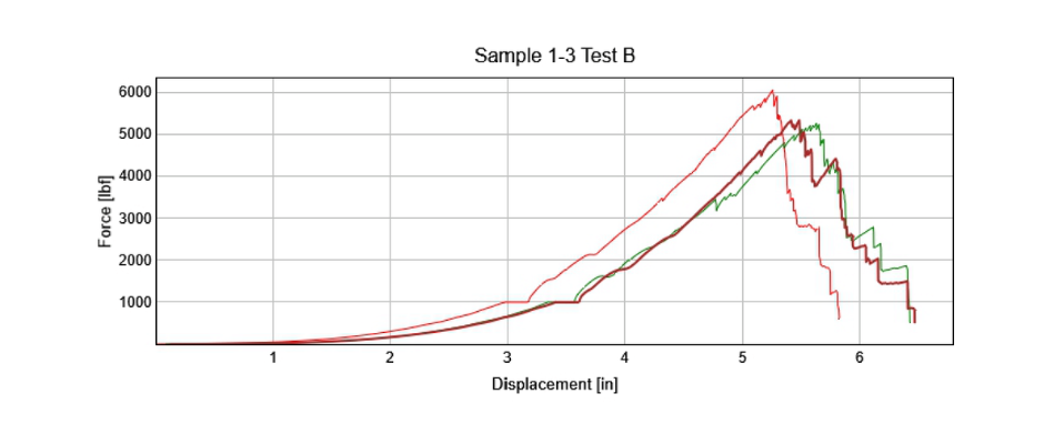
B. Leading Edge testing per ANSI/ASSP Z359.14-2014 was performed on 3 samples of X-7352 D1 that had previously been subjected to abrasion testing per FED STD 191A Method 5309. These samples were dropped with a 300lb test mass and allowed to swing unrestricted for a minimum of 2 minutes.
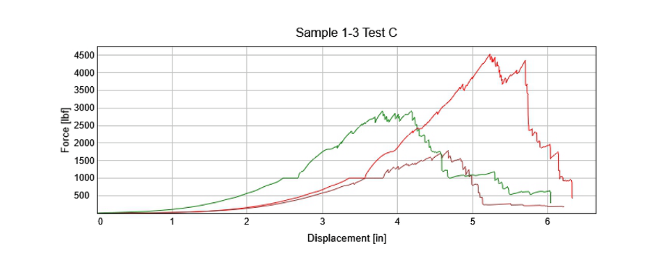
C. Leading Edge testing per ANSI/ASSP Z359.14-2014 was performed on 3 samples of X-7352 D1. This test was done with a 300lb test mass and allowed to swing unrestricted for a minimum of 2 minutes. At the conclusion of the 2-minute unrestricted swing samples 1-3 were subjected to the following.
Sample 1. Test Technician pushed the test mass to create a consistent back and forth swinging motion (perpendicular to the cutting edge) approximately 2’ in front and behind the face of the cutting edge for 1.5 minutes. At the conclusion of the 1.5 minutes using a webbing lead attached to the test mass, the Test Technician created a consistent circular swing in an approximately 4’ diameter for an additional 1.5 minutes.
Sample 2. Test Technician pushed the test mass to create a consistent side to side swing motion (parallel to the cutting edge) approximately 2.5’ in either direction from the centerline of the anchor point to which the sample is mounted for 1.5 minutes. At the conclusion of the 1.5 minutes using a webbing lead attached to the test mass, the Test Technician created a consistent circular swing in an approximately 4’ diameter for an additional 1.5 minutes.
Sample 3. Test Technician pushed the test mass to create a consistent side to side swing motion (parallel to the cutting edge) approximately 2.5’ in either direction from the centerline of the anchor point to which the sample is mounted for 1.5 minutes. At the conclusion of the 1.5 minutes, the Test Technician pushed the test mass to create a consistent back and forth swing motion (perpendicular to the cutting edge) approximately 2’ in front and behind the face of the cutting edge for 1.5 minutes.
*All swing distances are approximated at the location of the test mass Abrasion Testing Samples tested above in Section B were abraded using the Abrasion tester (Equipment ID: Q21) in accordance with FED STD 191A Method 5309. Prior to abrasion testing, the samples were marked to ensure that the abraded portion would line up with the section of webbing that would come into contact with the cutting edge at the swing portion of the Leading Edge test. Post Leading Edge Tensile Testing Samples were tensile tested using an Instron Model 5984 and split drum webbing clamps Q37 & Q38. Samples were pulled at a rate of 2”/min to 1000lbf and held for 1 minute. At the conclusion of the hold, time samples were pulled to destruction at a rate of 2”/min.
RESULTS

| Sample # | Force (lbf) | Observations |
| 1 | 5873 | Sample held 1000 lbf for 1 min. Failure Mode – Vectran gut partially pulled apart |
| 2 | 5318 | Sample held 1000 lbf for 1 min. Failure Mode – Vectran gut partially pulled apart |
| 3 | 5191 | Sample held 100o lbf for 1 min. Failure Mode – Vectran gut partially pulled apart |

| Sample # | Force (lbf) | Observations |
| 1 | 4508 | Sample held 1000 lbf for 1 min. Failure Mode – Vectran gut partially pulled apart |
| 2 | 1650 | Sample held 1000 lbf for 1 min. Failure Mode – Vectran gut partially pulled apart |
| 3 | 2807 | Sample held 100o lbf for 1 min. Failure Mode – Vectran gut partially pulled apart |


| Sample # | Force (lbf) | Observations |
| 1 | 6310 | Sample held 1000 lbf for 1 min. Failure Mode – Vectran gut partially pulled apart |
| 2 | 6339 | Sample held 1000 lbf for 1 min. Failure Mode – Vectran gut partially pulled apart |
| 3 | 5396 | Sample held 100o lbf for 1 min. Failure Mode – Vectran gut partially pulled apart |

